Two of these came up for sale at around the same time, one with the mottled paint look and one with a veneered wood design. I decided to go with this weird paint look as I have no other examples of this type in my collection and it looked like a game changer, lol A crocodile version came out in 1949.
It came with the back missing (a sign that it would be faulty and somebody already gave up on it), the paintwork was heavily scratched and a corner on the top front had a chunk of wood missing, but not one to give up on a challenge I took it on..
Resistors
|
Capacitors
|
|
| R1 220K |
C1 100 pf |
C11 0.001 uF |
| R2 22K |
C2 150 pf |
C12 8uF
(150v) |
| R3 47K |
C3
0.002 uF |
C13 450 pf |
| R4 2M5 |
C4
0.1 uF |
C14 150 pf |
| R5 5M
POT |
C5
0.1 uF |
|
| R6 47K |
C6 100 pf |
Valves
|
| R7 2M5 |
C7 100 pf |
V1 X14 |
| R8 1M |
C8
0.01uF |
V2 Z14 |
| R9 550R |
C9
0.0001 uF |
V3 HD14 |
| R10 2M5 |
C10 0.02 uF |
V4 N14 |
The set was made by Belcher Ltd, London who made radios from 1932-1949, little can be found about the company on line. This radio was battery powered using an all-in-one type such as an Eveready B114 that uses a 4 pin 1920s valve holder and plug that can be fitted to modern home made battery box (described later)
the repair
After applying 90 volts HT and 1,5 volts heater the set worked but very quiet with badly distorted sound. I cleaned the wavechange switch an volume control and applied an audio signal to the sound output valve Grid 1, that gave me plenty of clear sound, but bias the voltage on the grid was wrong, should be around -7 for pentodes. I checked the resistance between grid an chassis and it was low even with the valve removed, so I removed and checked the anode - grid feed capacitor (C10/ 0.002 uF) and it was leaky.
 |
| chassis removed, held on a wooden shelf that slides into a groove held by two wood screws |
|
 |
| faulty audio feed capacitor |
|
Before any repair make sure all the valves are correct and in the right places, it's time consuming but worth it in the end. I like to clean the valve, taking care not to rub numbers off and clean sockets and pins at the same time, one dirty pin will kill the reception.
I decided to fit 2 x LED's under Big Ben on the tuning dials. this was achieved with a magnetic on/off switch(so no need to put hole in back), battery box for 3 x 1.5 v and small gauge tinned copper wiring.
 |
| yellow led for MW and green for LW battery box for this fitted to loop aerial panel at rear with magnetic switch |
|
 |
| battery box made using a Tesco's microwave meal box with a 4 pin valve base |
|
 |
| damaged top was masked to protect paint then filled 2 or 3 times to a fine curved finish to be painted |
|
 |
| after masking removed ready for paint, light colour first followed by brown blobs and a wax coating |
|
Rust was treated on the carry handle and painted brown followed by a new carry strap made from an old belt. Scratches to the paintwork were removed using wood coloured felt tip pens.
 |
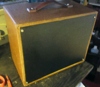
| new back made from plywood covered with car interior sticky backed vinyl |
|
 |
| this is how I fount the set on ebay, the seller told me that all the knobs were in the bag on the top,otherwise i don't think I would have taken it on. - happy days |
|

THE DIAL LIGHTS ARE ACTIVATED BY A ROCKING MAGNET LOCATED NEAR THE MAGNETIC SWITCH FITTED TO THE BACK OF THE SET


