

A post WWII battery portable with a box shape design with no frills. It uses low current miniature valves developed though the 1940's for military use. These are:- 1R5 (Mixer oscillator), 1T4 (IF amp), 1S5 (detector/amp) and a 3S4 (pentode audio output). All designed for 1.4 volt heaters and 100 volt HT supply's. 3 of the valves draw only 50 mA heater current and 100mA for the output pentode, so battery life was extended greatly, these valves are like the 1920's triodes in that they don't light-up or give off any heat, but 1920's valves used 200mA current each a big difference in energy saving. Due to the low power of the output pentode an efficient loudspeaker design is used, speaker grill being made from a woven painted wicker material that fights off aging more than cloth.
 |
| Impedance/resistance/capacitance tester from China (big time and cost saver) |

The first thing was to give it an all-over visual, this often reveals work carried out by previous repair men and lose connections. In this case I spotted a screw missing on the sound output transformer's base fixing, this had caused vibrations that had broken one speaker wire on the accompanying side. l also I found 3 resistors that were not going anywhere (possible mods to cure old faults) anyway as they were not shown on the circuit diagram I removed them. I was very lucky to find a circuit hidden inside the cabinet, it had been printed by Lasky's Radio, Harrow Rd, London? with a 1950's phone number (I wonder did they make this set? - or just helped somebody in the past, who knows now!). I re-soldered loop aerial wires back to their terminals on the cabinet as they had broken away.

The chassis is held in place by two small wood screws (one left, one right) holding a detachable wooden shelf that slides into grooves like a draw, sombody had extended the speaker wires in the past, so the whold chassis came away nicely. Looking underneath then having removed 3 bolts holding the draw to the chassis,. Inside it had about 10 x TCC wax covered capacitors that all read open circuit with my Chinese capacitance checker. (they can be found for just a few pounds on eBay, (without a cabinet) - best money I've spent in years). I also checked all the resistors and found a couple high in value and replaced them too. The 1R5 (V1) valve was missing, so I found an unused one 'on line' for £5.50 including postage.

The material covering the cabinet was totally undamaged, suggesting the radio may have been in store for many years, however the textured finish was covered in dirt/dust that was removed with a tooth brush and some warm washing up liquid in water. Take care when using modern cleaners with ammonia in, as they may remove the colour from dyed material (and text from dials). The two rusty handle covers were removed and cleaned with wire wool, in the past if they are too corroded I've spayed them a matching colour to the cabinet. Small tiny specs of paint collect over a lifetime of painting your home, these can be removed with your nails or a blunt piece of plastic (credit cards are good) I added some dabs of red to the carry handle strap with a felt tip pen where needed.
 |
| Showing missing bolt and broken speaker wire |
A real bonus with this radio is that it came complete with a Vidor battery power pack mains powered unit. It was designed to be the same size as the 90/1.4 volt original battery complete with a 4 pin socket for the radios plug to fit into. The bad news was, you guessed it, yes it didn't work. An internal combined 16/24 uF capacitor 350 volt working was open circuit, so two separate capacitors were fitted, no need to fit enormous one like the original, modern miniatures work fine, although high voltage low value capacitors are hard to find these days. The spare room left inside the power pack after new part was fitted allowed me to fit a 24 volt mains transformer to power two 12 volt bulbs in series for the tuning dial, a nice extra touch. I used a spare socket for the connecting wires that was fitted for other designed radios to be used with the Vidor pack.
 |
| Cost an 'arm and leg' at the time of release. (more than the radio cost) So well worth restoring |
 |
| Inside power unit showing 24 v transformer center bottom |
 |
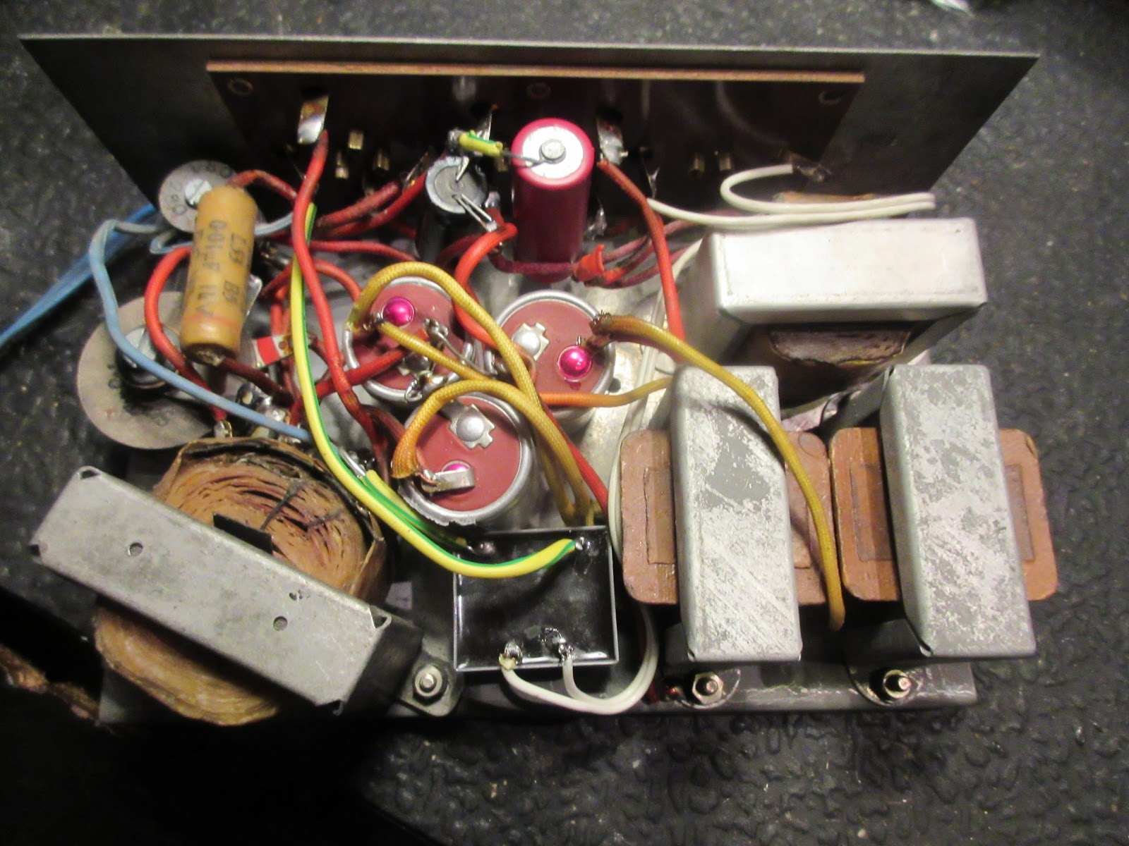
| Main chassis, silver electrolytic shows May 1950 as build date (wax C shown was also doggy) |

Middle Eastern radio station names on the tuning dial
 Tiny low cost mains transformer fitted in P-Pack, feeding two 12V model railway bulbs in series from a 24V AC winding
 Large faulty electrolytic capacitor removed from Vidor Power Pack
 |
| Just some of the faulty components pulled from the radio |


I like to show lots of pictures as they paint a 1000 words, I couldn't find another example of a HEC radio anywhere on the Net, just one model from 1923, if more turn up I hope this text will inspire or help another to be brought back to life. - good luck!
No comments:
Post a Comment