
Wireless Explained - Salmon & Gluckstein, Ltd, (London, 1923)
These cigarette cards were a wonderful. well illustrated set of 25 cards, one found in each packet of 10 cigarettes, it would have taken a lot of smoking to find a full set as repeats would frequently re-appear. Swapping with other collectors would have been a quicker way to make a complete set. Details on these cards was even better than found in notable book & magazines publications at this time. Reproduced here slightly larger than originals. Click on image for even larger views
No. 8. H.T. Battery.
A high-tension Battery consists of a number of small primary cells (A) connected in series to give a pressure of between 45 and 80 volts Placed in the plate of the circuit of the valve (Card 14) it forms a source of supply for the operation of the valve and telephones. It is sometimes made variable by tappings taken from various cells, usually even three volts Each separate cell consists of a zinc container with a carbon rod in the centre and sal-ammoniac solution, absorbed in porous wrapping between the rod and the zinc When the component parts become excused the battery is useless.
|
 No. 9. Fixed Condenser.
Generally a number of copper or tin foil plates (A) separated (B) mica or waxed paper (B). It i.-generally used as an electrical reservoir and steadies the flow of currents. The capacity of these condensers is calculated by the area of the overlapping plates between the dotted lines. The smaller illustration (Fig 1) shows the method of construction. (A) are the copper or tin foil plates, and (B) the insulating material, mica or waxed paper (C) and (D) are ebonite plates to keep the condenser compact and together. Wax is generally inserted at (E) to prevent the entrance of damp.
|

No. 22. Buzzer.
This consists of a coil of wire wound round a soft iron core, near which is placed a steel reed (A) Currents flowing in the coil from a battery magnetize the core and attract the reed, which automatically breaks the circuit, allowing the reed to return to its normal position. This action again closes the circuit and vibration continues as long as the battery is connected. It is used for testing crystal detectors. When the buzzer sounds its loudest in the phones the most sensitive part of the crystal is thus found Buzzer* sometimes contain two coils ot wire. b»it their action is the same.
|

No. 6. Coil Holder.
This instrument is a convenient method of holding the Tuning Coils (Card 5) They are made to hold two or three coils. The middle holder (B) is fixed, and the outer two (A) and (C) made to pivot so as to bring the coils closer to the fixed one. Greater selectivity is obtained by using three coils. With three coils in use (A) is known as Aerial or Primary. (B) as Secondary, and (C) as Reactance Coils.
|

No. 12. Crystal Detector.
A crystal detector is used to rectify or detect the incoming waves. It usually Consists of a fine copper wire (B) bearing on a suitable crystal (D) which will only allow currents to pass in one direction and thus operate the telephones (headphones) It is sometimes enclosed in a glass tube (A) to prevent dust collecting on the crystal. Sometimes two crystals make contact with each other and serve the same purpose. As a general rule a crystal detector will only receive music and speech up tn about 23 to 30 miles
|

No. 2. Earth.
Generally a thick wire (A), not necessarily insulated, connects to a plate (B) buried moist soil (C) and the soil being kept moist by water being poured on .it intervals. Another method is to solder wire to a water tap as in (D) or to fix an earth clip to a water pipe (E) A gas pipe is not advisable there is a slight risk of explosion should lightening occur. It is advisable to keep the earth connected when the set is switched off so as to a path for lightening if it was to strike.
|

No. 11. Grid Leak.
Consists of a very high resistance sometimes connected across the grid condenser (Card 10). or from the from the grid of the valve (Card 14) to the filament of same. It provides a path or leak whereby the electrons which collect on the grid condenser (Card 10) may return to the filament. It is usually composed of powdered graphite contained in a glass tube, contact being made at the ends by metal caps (C) An ebonite or wood .case usually covers the leak to protect it from the damp (A). The value of the leak is sometimes marked on it as in (B).
|

No. 10. Grid Condenser
This is generally a fixed condenser (Card 9) placed between the aerial terminal on the receiving set and the grid of the valve (Card 14) It is sometimes bridged by a very high resistance known as a grid leak (Card 11} This condenser is used to prevent the flow of direct currents to the grid of the valve (Card 14) It is only used when the valve is used to rectify the incoming signals Clips (A) are to hold the Grid Leak (Card 11) The grid leak is shown dotted in the circle.
|

No. 3. Loose-Coupler.
In order to receive signal from a given transmitting station the receiver must be adjusted to the required wave-length of that station. To do this a loose-coupler is sometimes employed. The type indicated consists of more cylindrical coils (A) and (B) wound with insulated copper wire (B)being made to side-within (A) which is used to tune the aerial to the required wave-length and (B) to tune, the receiver. The wave-length of (A) is made variable by a slider (C) and in (B) by studs and a movable contact arm (D). Greater selectivity is obtained with a loose-coupler.
|
 No. 25. Microphone.
Is a device for transmitting sounds The waves collected by the mouth piece (C) set the disc or diaphragm (A) in vibration, pressing it inwards in concave form or else causing it to bulge out again. Behind the diaphragm (A) are carbon discs, and between these discs the space (B) is filled with small granules of graphite, carbon or coke. One wire is connected to the carbon discs and the other to the diaphragm. When the diaphragm vibrates this action causes the granules to be squeezed together and their electrical resistance varies, thus causing disturbances in the circuit called sound waves.
|
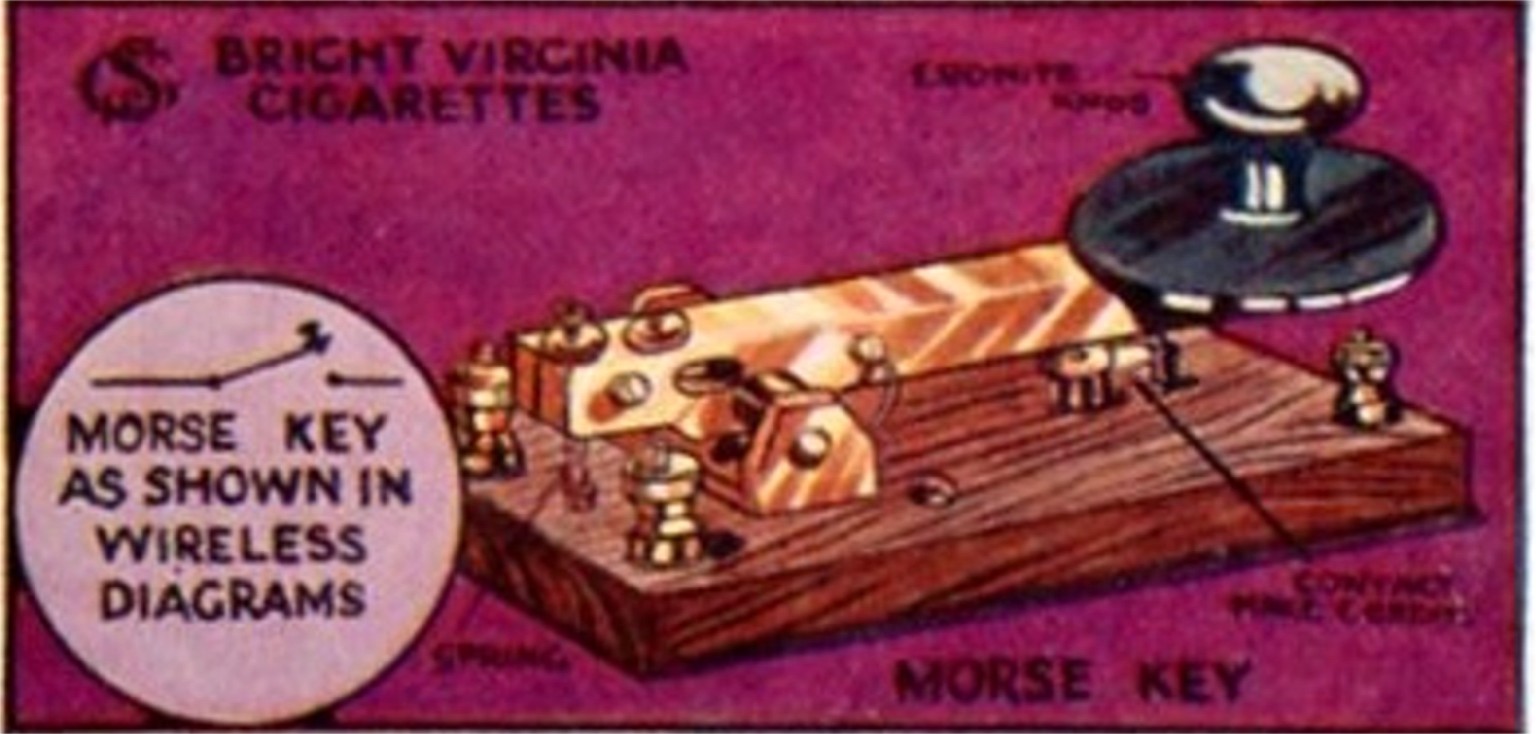
No. 11. Morse Key.
The Morse Key is a switch by which dots and dashes are produced from the transmitting station. Before the advent of telephony it was the only means of sending signals. By this key the operator switches on or off the currents produced by the generator. These currents can be made to flow up and down the aerial for long or short periods as desired, and so dots and dashes are produced, the dash is uselessly three times as long as a dot. Wireless is made very interesting if the listener can read 'Morse Code'. A good way of learning is to purchase a key, a buzzer, and a dry cell, connect these up and practice reading dots and dashes by a second person. Aim at correct reading first an speed will come with practice. |

No. 24. Telephone Receiver.
A telephone receiver (working principle shown in diagram C) consists of coils of fine insulated wire (1), wound on a steel magnet (2). The currents flowing through the wire operate the magnet, thereby causing the diaphragm (3) to vibrate (4). These vibrations cause sound waves to be .transmitted from the receiver. (A) and (B) show the interior and section of a " Watch-case" type of receiver. As used for Wireless two of these receivers are joined together by a headband, leaving the hands free to operate the various controls of the receiver.
|

No. 17. Potentiometer.
When used in conjunction with small battery in crystal circuits, it is for the purpose of placing a small amount of current across the crystal to enable it to rectify or receive efficiently. Carborundum is about the only crystal which needs a Potentiometer. It is also used in valve circuits to give the grid of the valve a small charge of electricity. It consists of a coil of fine resistance wire (A) wound on a former. It is made variable by means of a slider (B). Usual resistance value is about 300 to 500 ohms.
|
No13 Telephone Transformer.
An instrument consisting of (A) primary (1st) and (B) secondary (2nd) winding's of very fine insulated copper wire, wound on a core of soft iron wires or plates (C). The primary usually contains more turns than the secondary. This transformer is used with low resistance telephones (150 ohms resistance value of winding's in telephones Card 24), and prevents the risk of damage to telephone- winding's by the direct passage of current the high-tension battery (Card 8)
|

No. 15. Filament Resistance.
A device placed between a valve filament {Card 14) and the accumulator (Card '20) to limit the supply of current to the filament. By this means the best temperature for the filament necessary is found for the best reception.
It consists of a resistance wire (A) having a resistance of about 5 to 10 ohms, according to the number of valves in use. The resistance is made variable by the slider (B) which passes over (A) Another type is shown in Fig. 2
|

No. 20. Accumulator.
This is a store of electricity, usually from 4 to 6 volts, and is connected to the valve filaments in order to maintain the filaments at a correct temperature necessary to operate the valve. It consists of a number of positive plates (B). and negative plates (A), immersed in diluted sulfuric acid Unlike the dry battery (Card 8). the component parts of the accumulator are not consumed in action. When run down all we have to do is to pass current through it (from the electric light mams), in the "wrong" direction and the lead plates are restored to their original condition

No. 16. Frame Aerial.
Generally a number of turns of wire (A) stretched on a wooden frame (B) Its thief advantages are portability and freedom from jamming or interference of other stations. This fact is due to directional properties, as signals will be received only from those directions in which, opposite sides of the frame aerial are facing. A convenient size for the frame is 4' square. It must be remembered, however, that signals obtained on a frame aerial are generally very much weaker than those obtained by an ordinary open aerial. A frame aerial is practically of no use with a crystal detector.
|
No. 18. H.F. Transformer.
This is a device for coupling two valves to increase the range of the receiving set. It consists of two winding's each of same number of turns wound together on ebonite former. One of the winding's is usually tuned to he correct wave-length of the incoming signals by a variable condenser (Card 7)j Sometimes these transformers are are fixed, but generally variable. The interchangeable type (B) is made to fit an ordinary valve holder, a set of about 8 of these will cover all wave-lengths.
 No. 1. Aerial.
The Aerial serves as a collector of the Wireless waves sent out from a transmitting station and usually consists of one or more wires (A) suspended at a fair height in the air between two tall buildings, poles or trees as may be convenient. The wires are well insulated at (B) A leading-in wire (C) is taken from the end or absolute middle to the receiving set. Greater efficiency is obtained if the aerial points direct to the station from which you wish to receive signals.
. 
No. 4. Variometer.
A variometer is sometimes used as a tuner in place of a loose-coupler (Card 3). It consists of two coils (A) and (B) wound with insulated copper wire, an end of one being connected to the one end of the other, the two free ends (C) and (D) being connected to the receiver. One coil (A) is made to rotate inside the other (B). Varying the position of the coils length. When using this a variable condenser (Card 7) is not really necessary. |

No. 7. Variable Condenser.
This instrument consists of a number of half-cylindrical aluminium plates, half of these (A) are fixed to a spindle and are made to rotate between the other plates (B) (without touching them) which are fixed. The condenser is shown in a mica case to prevent the entrance of dust. These condensers are used to vary the wave-length of the tuning coils (Card 5). When using these a very fine adjustment is possible.
No. 19. L-F. Transformer.
This is a coupling device between two valves whereby the signals after being rectified or detected are magnified usually bout five times, the transformer
consists of two winding (B) of fine insulated copper wire wound on a core of soft iron or plates (A). One winding contains more turns than the other These transformers do not tend to increase the distance covered by the receiving set, but the volume of the received signals. (C) are for soldering wires to ensure good connections.
|
 No. 21. Loud Speaker.
It is sometimes a telephone receiver with a horn attached. The various properties of the horn magnify the volume of sound emitted from the ear-piece, there-by permitting a larger number of people to enjoy the various items received. The loud speaker shown has the receiver permanently fixed in he base, the diaphragm of which is made adjustable (by the lever B). to vary the tone of the received signals. (A) is the cord to attach the loud speaker to the receiving set.
|
No. 14. Valve.
The valve is a vacuum tube of glass containing a filament, grid and plate. The grid is usually a wire spiral surrounding the filament. and the plate (or anode) consists of a metal cylinder surrounding both filament and grid, neither of these touching each other. The valve when used in Wireless receiving sets is to detect (or rectify) and magnify the incoming waves by passing them in one direction only and thus operating the telephones. There are various types of valve and the one illustrated is known is " R " type receiving triode valve.
| 
No. 5. Tuning Coil.
The illustration shows what is generally known as honeycomb coil. These coils are of a fixed wave-length required by a variable condenser (Card 7) These coils are interchangeable and are made to plug in the coil holder (Card 6) There are various other tuning coils, a very efficient one- being a cardboard former wound with insulated copper wire and made variable by the aid of one or more sliders A variable condenser (Card 7) is used in conjunction with these coils to obtain very tine adjustment.
|

No comments:
Post a Comment